
To the average computer user, motherboards’ complex designs, confusing acronyms, and unfamiliarity convey a kind of cosmic horror that even Lovecraft would be proud of. And with dozens of models available for most platforms, understanding modern motherboards can be difficult unless you’re passionate about PC hardware. But understanding the motherboard can be a rewarding experience, as the motherboard is a component common to all computers. Every computer system, from smartphones and smart devices to room-sized workstations, sits on a motherboard. In a sense, it is the foundation of modern computers, and having a good knowledge of motherboards can help you not only learn how computers work, but also help you understand the complex interrelationships of PC components.
What is a Mother Board: Guide to all Ports and Connections:-
What we are trying to do with this article is a detailed breakdown of motherboard structure covering all the major ports, headers and slots common in today’s hardware. This breakdown, we believe, will help uncover the genius of modern motherboards. This will not only help you understand the motherboard better but also give you a new level of appreciation for the hardware.
Defining a Computer Motherboard:-
Simply put, a motherboard is a large printed circuit board (PCB) that connects all the other components of your PC together, such as the CPU, GPU, RAM, and storage. Think of it as the nervous system or circulatory system of a computer. The motherboard ensures that all these components are speaking the same language and that the systems are working together properly. It does this by simply controlling the amount of power and data passing through the circuit board. This is done through thousands of small strips of copper wire sandwiched between multiple layers of the substrate that make up the motherboard. If you look close enough at the motherboard, you’ll see some traces that run along the top layer.
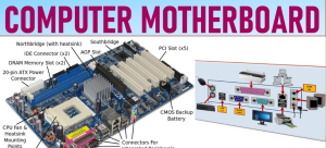
Below we have an image of a modern motherboard, specifically, a modern ATX board. Although it is a specific form factor, most modern motherboards are very similar in general design connections and design philosophy. So for the purposes of this article it should do.
A Brief History of the Mother Board:-
In our popular perception of a computer, the motherboard has always played an important role. Its image has long been associated with the complex, mysterious interior of the system. But as we’ll explore in this section, the modern motherboard, while giving the impression of an old concept, was actually invented long after the first computer.
Early computers were more complex in terms of components than modern machines and consisted of multiple circuit boards connected to each other by a backplane, a set of interconnected sockets. This meant that the CPU, memory and peripherals were placed on their separate boards.
This changed with the advent of the microprocessor. As microprocessors became more powerful, they were able to execute workloads that were previously done by dedicated hardware. This made it more economical for computer manufacturers to build a single large board with all the functionality and connect it together via a backplane, rather than making small dedicated circuit boards.
The IBM Personal Computer (1981) contains the first motherboard that we know of. At first, this material was called a planar and at the beginning of its creation, went through many additional names. However, the term that stuck was “motherboard” because the board basically acts as the mother of all the other components of the computer. And this is the main reason why the small boards attached to the motherboard are sometimes known as daughter boards.
The motherboard of an IBM PC contains the computer’s CPU and RAM, provides audio as well as other essential functions, a keyboard, and ports for cassette tapes. This board even had expansion slots for add-on cards as well as a system called a bus to manage this data flow.
The IBC PC was a revolutionary machine that changed the future of computing. Perhaps this is why the original IBM PC, with its simplicity and openness, set the standard for many computer hardware specifications in “IBM-compatible” computers, and its famous moniker “PC” came to be a single term to describe computers. come year.
Different Sizes of Mother Board:-
Motherboards may be simpler than the giant computers of yesteryear, but at first glance, they still look like a complex object, and frankly, they are. It’s a maze of circuitry that’s both overwhelming and fascinating. But when it comes to motherboard size or type, the situation is much more understandable.
Although historically motherboards have come in a variety of sizes, such as IBM’s Baby ATX or Intel’s NLX boards, most consumer motherboards today come in one of three sizes: ATX, micro-ATX, and mini-ITX.
The ATX platform is the most popular of them all and has been the industry standard for some time. It offers a lot of flexibility when it comes to expansion and upgrades, making this form-factor a favorite for gamers and other PC enthusiasts. Mini-ITX, on the other hand, is the smallest of the bunch, and is typically used in compact PC builds.
Finally, the micro-ATX form factor splits the two down the middle and gives you some flexibility when it comes to PCI-e and RAM expansion, and keeps the overall size smaller than full-ATX motherboards. Additionally, one may also come across E-ATX motherboards, which are larger than Full-ATX, but primarily used in workstation systems. Other form factors still exist, such as the mini-STX, but they are so rare that they are not available in retail stores.
Mother Board Ports and Connections:-
Over the years, the number of different ports and their design have changed due to the development of technology. Older and outdated ports like serial ports have given way to USB, and relatively new standards like SATA are being replaced by newer technologies like M.2. In the ever-evolving face of computer technology, everything is ephemeral. But that doesn’t mean knowing today’s ports is useless.
These ports form the basics of a desktop computer, and we’ve listed some of the most important connections you can find on your motherboard. To make it easier to understand, one can divide the motherboard ports into three distinct categories.
-
Slots /Ports:-
These are usually raised ports that originate from the motherboard and can accommodate various hardware components. Depending on the age of your motherboard, the main slots and ports you will find may be – PCIe (Peripheral Component Interconnect), RAM (Random Access Memory), SATA and M.2. Older motherboards may have other ports such as AGP (Accelerated Graphics Port), which have been almost completely replaced by PCIe on modern motherboards.
-
Sockets:-
These are openings on the motherboard that allow users to install component pieces directly onto the motherboard. The most notable example is the CPU socket.
-
Connections:-
Connections provide power to your components through your power supply. These are often pin connections, some of which are placed in raised sockets, while others are bare, such as the power and reset pins.
CPU Sockets:-
We’re going to start this breakdown with the most important part of the motherboard, which is the CPU socket, also known as the CPU slot. It is a part of the motherboard that contains the necessary terminals and parts to hold the CPU. As you can see in the image below, this socket is easy to spot on most motherboards because it has a distinctive design and covers a large surface area.
CPU sockets these days come in two variants — LGA (Land Grid Array) and PGA (Pin Grid Array). What differentiates these two is the arrangement of the contact pins. Depending on the type of processor, these pins are either in the socket or under the CPU die. For example, with LGA, you have contact plates on the bottom of the processor and on either side of the CPU socket.
On the PGA, which is typically used by AMD, the small pins are located on the bottom of the CPU, which go directly into the small holes in the CPU socket. The PGA CPU socket is highlighted in the image above.
There are different versions of sockets between the two socket types, and different sockets affect the CPU’s output performance. For example, within the LGA socket type, Intel offers many variants with different pin setups. All new motherboards usually come with the latest socket type that allows you to pair the motherboard with newer, more powerful CPUs.
For example, as mentioned above, the ASUS motherboard in our example comes with an LGA 1700 socket (the number represents how many pins are in this socket) that works with 12th-gen Intel Core processors, enabling you to use Intel’s latest and greatest. Hardware In the image below, you can see a close-up of the Intel LGA 2011 socket
In general, the more capable the CPU, the more pins available in the socket. This was the main reason Intel used the LGA 2011 socket in the HEDT processor lineup, which had almost double the pin count of the then-current LGA 1151 socket. For example, a larger number of pins allows the processor to access more power from the power supply because more power delivery pins can be assigned to the processor.
However, pin increase is not the only way to measure performance increase. For example, AMD stayed with the same 1331 pin layout from Ryzen 1, which was released in 2017, but with a significant increase in performance over the generation.
RAM Slots:-
The second important part of the motherboard that we will discuss is the RAM slot. These are usually located right next to the CPU socket. Random access memory (RAM) is basically a form of very fast memory that stores data so that applications can access it quickly.
RAM is different from storage like an SSD or HDD because it is volatile, meaning it loses data when the power is turned off or the computer is reset. Programs and applications, from word processors to games, all need RAM to run smoothly. The amount adds up quickly, so if your PC doesn’t have enough RAM to run open applications, it will suffer from slow speeds and often experience crashes.
Modern memory slots look like the one we see above (marked in red) and have a clip on one side that is used to hold the memory stick in place. The other side is usually perforated to hold the stick in place but allows the memory stick to be pressed into the slot without the need for a second clip like on older motherboards (shown below).
In the example above, the CPU mounted on this motherboard has two memory controllers. And each handles 2 sticks of memory, so, there are 4 sockets in total. Also, you can see that the memory sockets are color coded to let you know which one is handled by which controller. These are commonly called memory channels, so Channel 1 (colored blue) controls these two slots and Channel 2 (colored gray) controls the other two. The channel closest to the CPU socket is usually channel 1 and is where you should install the first stick of memory.
Power Connectors:-
To provide the voltage and current needed to run the motherboard and the many devices attached to it, the computer’s power supply unit (PSU) has several standard connectors for this purpose. 24-pin and 8-pin connectors 24-pin and 8-pin connectors are available on all modern motherboards such as the Z690 shown below.
The main one is the 24-pin ATX connector located on the right side of the motherboard. Although the connector has 24 pins, depending on the computer, they can use anywhere from 20-pin to 11-pin on small towers.
8-pin, on the other hand, exclusively powers the CPU and is usually located on the upper left side of the motherboard. The 8-pin connection can be a 4+4 pin, although some high-end CPUs even have an 8+4 pin connector.
PCL-Express Slots:-
PCIe Express sockets are long RAM-like connectors just below the CPU socket. Every desktop motherboard has at least one PCIe slot and can be used to add other PC components to the system, such as GPUs, Wi-Fi cards or PCIe SSD (solid state drive) add-on cards. PCIe is basically an interface standard used to connect these high-speed components to the CPU.
The type of PCIe slots available on your PC will depend on the motherboard you purchased. But the main physical configurations they come in are: x1, x4, x16, and x32. The number after x indicates how many lanes the PCIe slot has – the higher the number, the faster the connection can achieve. In the current PCIe gen 5 standard available on the latest Intel processors, bandwidth can go up to 120 GB/s in a 16x configuration.
Cards and slots can be mixed and matched regardless of the number of lanes indicated by each component, with data bandwidth determined by the slowest part. For example, if your motherboard has a PCIe x16 slot, you can connect a PCIe x1 card. Here, your bandwidth will be limited by the card’s single available lane, which is one bit per cycle. Similarly, if you put a PCIe x8 card in a slot that is either x1 or x4, the data will travel 1/8 or half the bandwidth compared to inserting it in the default x8 slot.
So what are the common use cases for these PCIe sockets? As we’ve already mentioned, the PCIe socket is an incredibly flexible platform that can be filled with numerous expansion cards.
You can see the difference between the connectors in the image above. The graphics card sports a long x16 lane standard compared to the short 1-lane setup of the storage card. Because a storage card transfers much less data than a graphics card, it doesn’t need all those extra lanes.
SATA and M2 Slots:-
Different motherboard configurations place the SATA ports differently, but you can always note it, given its unique plug and onboard labeling. The small hole in the plug determines its orientation. Here on our reference motherboard, the SATA ports are located on the right side of the motherboard.
SATA ports were the primary data transfer ports for years and were used with all kinds of different hardware, from CD ROMs to expansion ports and hard drives. They are still very common in most computer builds, and to this day, form the backbone of computer storage on most motherboards.
The standard that has taken over the storage standard baton from SATA is the M.2 slot. Formerly known as the Next Generation Form Factor, the M.2 standard has taken the PC world by storm. And in a very short time, it has become the dominant storage standard in both desktop and laptop PCs. The reason it is so popular is multifaceted. Not only is the slot small, it’s also flexible as it can interface with both the older SATA 3.0, PCIe 3.0 , and even USB 3.0. Most newer motherboards have at least one M.2 slot, but some high-end motherboards may have up to 4 slots.
MotherBoard Fan Headers:-
Next is the motherboard fan header. These connectors are either three- or four-pin modules that usually sit on top of the CPU socket. Ironically, they are used to power the cooling fans inside your computer, although you can also use them to power other components such as water pumps and RGB lights. One can think of them as mini 12V power connectors originally designed for hobbyists, only now they have different uses.
In the image above, we can see that the CPU fan header is present at the top right of the CPU socket. It is labeled CPU_FAN and CPU_OPT. There are other fan headers across the motherboard and are usually labeled as SYS_FAN.
Now, the only real differentiating feature between the CPU fan header and other fan headers is that there is an inbuilt failsafe to protect your CPU from damage to the CPU fan, if the CPU fan header does not have a fan plug the computer will not boot. . . For chassis fans, you should use the SYS_FAN headers, as they are located all over the motherboard making cable management easier depending on where your fan is located.
Another thing you need to remember about fan headers is the difference between 3- and 4-pin headers. The 4 pin fan header supports pulse width modulation, which acts like a switch, turning on and off while controlling the amount of power supplied to the fan or pump. This allows fans with 4 pin headers to achieve seamless speed control, which is difficult to achieve with 3 pin fans.
VRM and MOSFET:-
The next part of the motherboard we see is not a connector or port, but an important part of the motherboard that makes it work – the VRMs. Now, VRM is a term that gets thrown around a lot in the overclocking community, and if you’re into it, you’ve probably come across it.
So what is a VRM? The term stands for voltage regulator module and describes an electronic channel that regulates and modifies the mains voltage received from the power supply. In current-gen power supplies and motherboards, this means taking 12V current and converting it to 1V for the GPU or 1.4V for the CPU. The process of conversion is complex, but the principle that voltage regulation circuits rely on is the ability to reduce the average output voltage of the circuit by switching the input voltage off and on.
That means if you have a 12 V output and you turn it off and on for equal parts, the average voltage will be 6 V. This rapid change in voltage is accomplished by a metal oxide semiconductor field effect transistor circuit.
Since our reference motherboard does not have a visible VRM module, we used a different image to demonstrate the same. Here, you can clearly see the MOSFET transistor and the capacitors used to convert the voltage. As they deal with large amount of current they tend to get hot and this is the main reason why they are usually accompanied by many heat sinks.
Motherboard Rear1/0 Ports:-
Now, we will look at the main I/O panel of the motherboard, which is almost always located at the back. This is where you will connect most of your peripherals including keyboard, mouse, display, etc. The layout and number of ports may vary depending on your motherboard model, but since we are using a high-end motherboard as a reference, this is a recent generation motherboard. Should cover most of the currently available ports.
-
USB Ports:-
The first set of ports we’ll see on the rear I/O are the USB ports, which come in different colors and at least two sizes. Note the standard rectangular USB-A ports; Different versions are identified by port color, but USB ports and most devices are backwards compatible.
The USB Type-C port – an oval port to the right of the blue USB port – is another USB available on most modern motherboards. Although USB-C ports are new, they function similarly to their more common brethren, but are capable of transferring data at higher speeds and transmitting higher levels of power.
| USB Colors | Features |
| Black | USB 2.0 with speeds up to 480 Mbps |
| Blue | USB 3.0 with speeds up to 5 Gbps |
| Teal | USB 3.1/3.2 with speeds up to 20 Gbps |
| Red | USB 3.2 with speeds up to 10 Gbps, Always-on charging port |
-
HDMI/Display Ports:-
Looking at the left side of the panel, we have the video port. Here are pictures of two more modern video connections, HDMI with Display Port on the bottom or DP on the top Although most motherboards have video ports, many high-end CPUs no longer come with integrated graphics, instead relying on a dedicated video card and its display port to power the display.
-
RJ45 Ethernet Port:-
Next, we can see the Ethernet port. This is where the network cable will plug into your computer. Virtually all motherboards will have one of these RJ45 Ethernet ports because desktops typically rely on a wired connection to the Internet. Ethernet still offers the best network speed and connection stability.
The current industry standard for a decent Ethernet connection is a gigabit port, but some high-end motherboards may also come with 2.5 gigabit Ethernet or 10-gigabit Ethernet ports.
-
Wireless Connectivity:-
Right next to the RJ45 port, we have the Wi-Fi and Bluetooth antennas. They enable your computer to connect to a wireless network without installing any additional hardware, such as a PCIe Wi-Fi card. Now, Wi-Fi on motherboards can be expensive and that’s why many budget motherboards don’t have this feature.
-
Audio Ports:-
For our last item on the back panel, we see the audio ports. The reference board we’re using has several connectors, but mostly it depends on your sound setup. Almost all motherboards on the market today use the same standard color scheme for audio ports. Green is usually used for audio-out and red or pink for audio-in. There are ports for additional hardware such as subwoofers or additional speakers.
Conclusion:-
Hopefully, I was able to tell you about the motherboard website. You have found the site you are on. And if you want to know anything, you can ask with the help of comments below.